Master C5000 Dispenser Installation Manual For 40 to 160 Litre Models
Introduction
This installation sheet provides essential instructions for setting up Compac’s Master C5000 Dispensers with flow rates ranging from 40 to 160 litres per minute. The document outlines key installation requirements including mounting, electrical connections, and piping arrangements. Designed for commercial fuel dispensing environments, it ensures compliance with safety and performance standards. Clear diagrams and step-by-step directions are included to assist technicians in installing the dispensers correctly. This guide should be used in conjunction with local regulations and other Compac support materials. Make sure you are familiar with the Conditions of Use.
It applies to the following models:
- MR40S (std, marine and aviation)
- MR80S (std, marine and aviation)
- MMR40S (std and marine)
- MMR80S (std and marine)
- MMR40-80S (std and marine)
- MMR160-80S (std and marine)
- MMR160-40S (std and marine)
- MR160S (std, marine and aviation)
- MMR160S (std and marine)
NOTE: Do not use this manual for earlier models. Contact Compac for archived manuals if required.
Product Identification
Ensure you are using the correct installation instructions and footprint drawing before commencing site work or installation. The identification plate is fastened to the bottom of the right-hand side panel when facing the front of the dispenser. Get more information on identifying your product here.
Installation
Static Electricity Precautions
Electronic components used are sensitive to static. Please take anti-static precautions. An anti-static wrist strap should be worn and connected correctly when working on any electronic equipment. If an anti-static wrist strap is unavailable, or in an emergency, hold onto an earthed part of the pump/dispenser frame whilst working on the equipment. This is not a recommended alternative to wearing an anti-static wrist strap. NOTE: Compac Industries Limited reserves the right to refuse to accept any circuit boards returned, if proper anti-static precautions have not been taken.
Pre-installation Check
Once the pump is received on site, check that no damage has occurred while in transit – in particular, damage to electronics due to vibration or jarring. All terminals and plugs should be checked, including IC chips, to ensure they are securely in place.
Procedures
Installation should be in accordance with local regulations.The dispensing equipment shall be installed to prevent the delivery hose from contacting the ground when not in use. Where local regulations require a sump to be fitted:
a. Sumps must be provided at all dispenser installations with secondary containment pipework and at all new installations.
b. At all sites with sumps, dispensers must be installed with a liquid level detection device fitted in the sump that will raise an alarm if liquid is detected in the base of the sump.
c. All Compac Master dispensers at automotive sites must have a safe break device installed in the delivery hose.
d. External pump systems required to have an automatic emergency shut-off device installed at the base of each dispenser and it must be activated if the dispenser is knocked over or pulled from its mount.
Dispensing Hoses and Nozzles
The unit may or may not be supplied with dispensing hose and nozzle assemblies. If customer supplied hose assemblies, pylons, reels, safe breaks and nozzles are used they must comply with the requirements outlined in AS/NZS 2229. All dispenser nozzles must trip shut when returned to the nozzle holder.
Breakaways
For all dispensers fitted with breakaways, ensure the breakaway is installed between the nozzle and the high-mast or pylon (if fitted). Any breakaways that have been subject to a break-away situation should be inspected and refitted or replaced in accordance with the original manufacturer’s instructions.
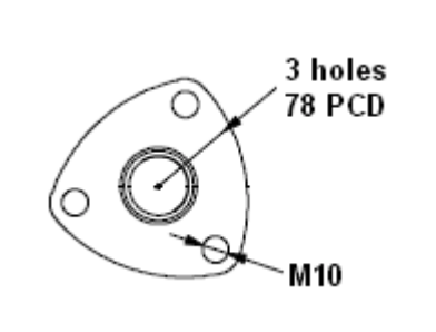
Footprints
Outlets
Outlets are 680mm above the base.
Outlet sizes: 40 l/min ¾”, 80 l/min 1”, 160 l/min 1 ¼” female BSP socket
NOTE: Make sure the footprint you use matches the dispenser model you are installing.
NOTE: Marine and aviation 160lpm dispensers use stainless steel pipework and sockets instead of a flange.
Footprint Sketches
The following footprint drawings provide essential layout, connection, and mounting information for a range of Compac dispensers. Each diagram is designed to assist with accurate installation and integration into site infrastructure, including standard, marine, and aviation variants.
- Master PN4 MR80S & MR40S Dispenser Footprint Drawing (Includes 'Marine' variants)
Outlines the key layout and nozzle positions for MR80S and MR40S dispensers, including marine options.
- Master PN4 MR80S & MR40S Aviation Dispenser Footprint Drawing
Provides installation dimensions and nozzle outlet locations specific to aviation fueling setups.
- Master PN4 MR160S Dispenser Footprint Drawing (Includes 'Marine' variants)
Shows layout and connector positions for the MR160S dispenser in standard and marine configurations.
- Master PN4 MR160S Aviation Dispenser Footprint Drawing
Details the dimensions and connection points for MR160S units used in aviation refueling systems.
- Master PN4 MR160S Aviation Dispenser Footprint Drawing (Left-Hand Outlet & Nozzle Holder; N.Z)
Provides footprint details for MR160S units with left-hand outlet and nozzle holder, specific to NZ sites.
- Master PN4 MMR80S, MMR40S & MMR80-40S Dispenser Footprint Drawing (Includes 'Marine' variants)
Includes layout specs for the MMR80S, MMR40S, and MMR80-40S dispenser models with marine options.
- Master PN4 MMR160S Dispenser Footprint Drawing (Includes 'Marine' variants)
Shows layout and mounting information for MMR160S dispensers, including harsh environment variants.
- Master PN4 MMR160-80S & MMR160-40S Dispenser Footprint Drawing (Includes 'Marine' variants)
Details footprint layouts for combined MMR160-80S and MMR160-40S models, including marine setups.
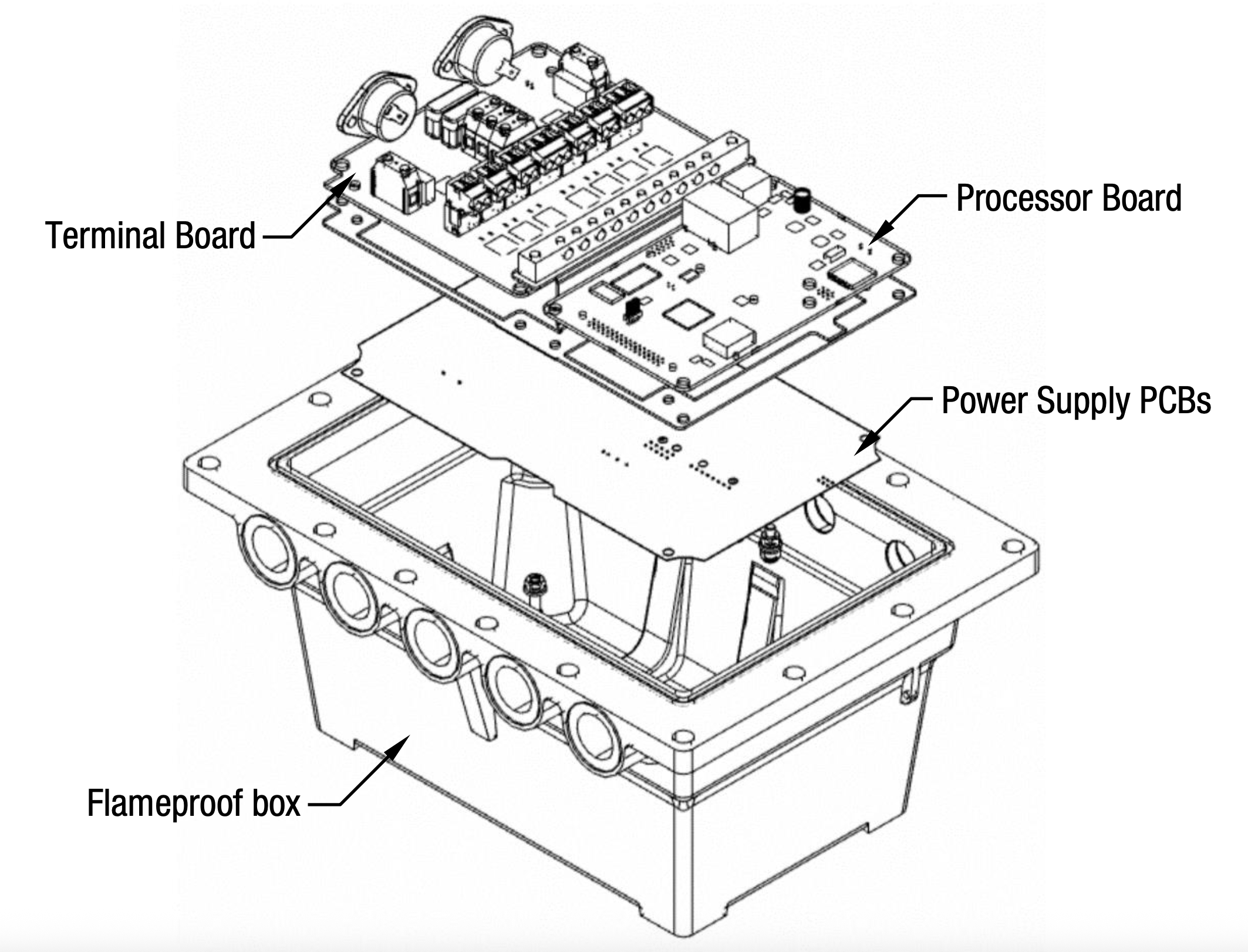
Typical wiring
The instructions below refer to basic installation wiring. Prior to pump installation ensure that there is at least a two-metre tail on both the incoming underground mains supply cable and comms cable (if comms enabled). These cables are terminated at the C5000 power supply, which is housed in the flameproof enclosure located in the bottom of the pump, behind the door.
Mains power wiring should be rated for a maximum current draw of 10 A rms at 220-240 V ac.
Refer to AS/NZS 60079.14 for appropriate cabling.
NOTE: All cables entering the power supply must be glanded with certified 20mm flameproof
glands.
NOTE: Output to submersible pump(s) is 230 V ac, 300 mA max. It is wired to the pump
contactor/relay at the switchboard and not directly to the pump.
NOTE: Comms cable is not intrinsically safe.
NOTE: Pump comms connects to pump controller such as DCA, Communicator Controller etc (option)
When replacing the lid of the flameproof enclosure, ensure the sealing O ring is in place.
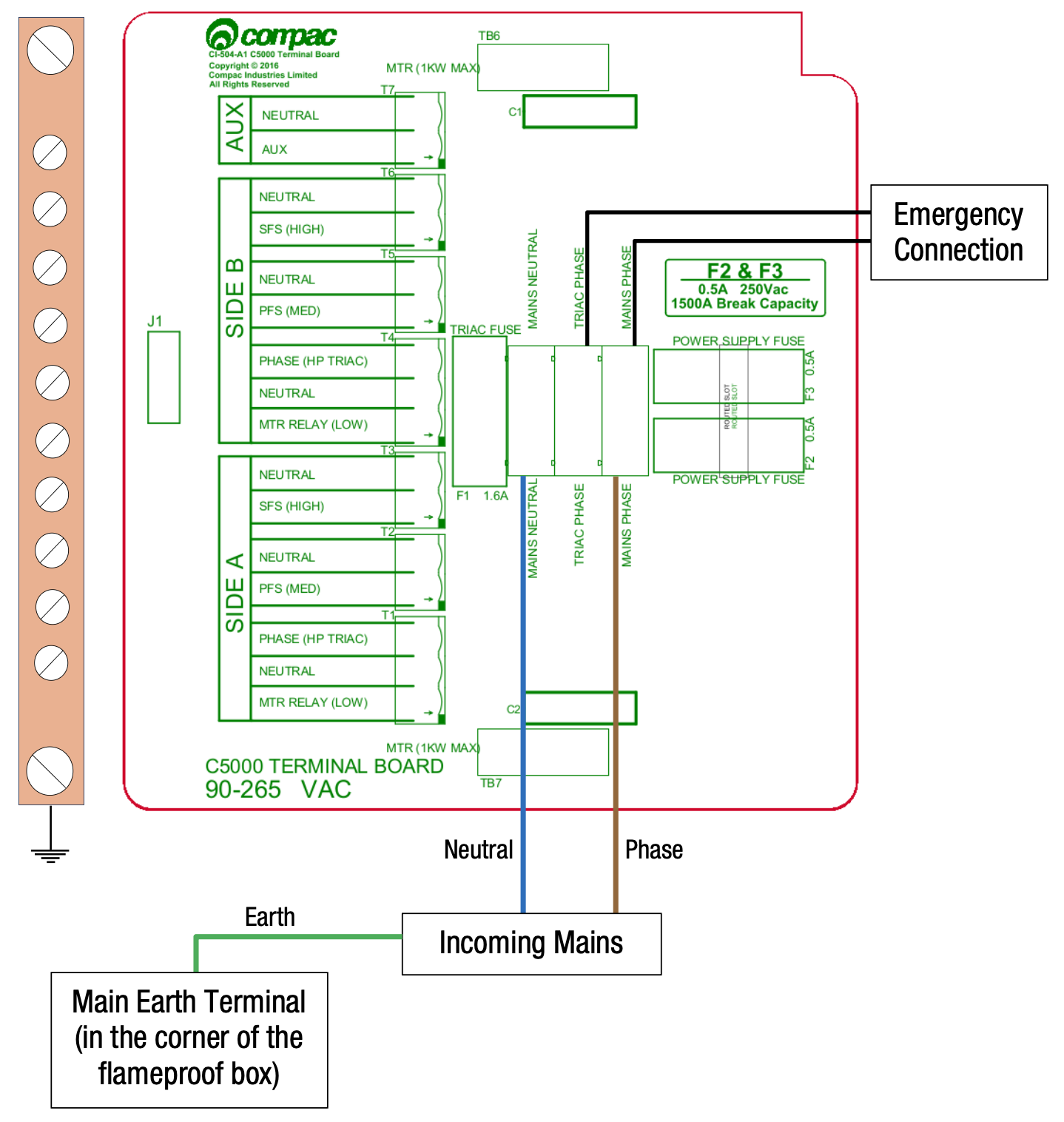
Incoming Mains
Incoming mains connections should be brought in to the terminal board. If an emergency stop button was ordered with the dispenser it will be factory wired into the
terminal board, shown below. This will be in place of the normal loop between the triac and main phases. Wires have standard colours which are shown. In case these colours are unclear, they are as follows:
-
Incoming mains phase: Brown
-
Incoming mains neutral: Blue
-
Incoming mains earth: Green/Yellow
Comms Connections
The comms I/O is controlled by the connections to the Comms board. Refer to the following diagram for connecting RS485, RS232, Compac or Gilbarco pumps. The shown switch should be set to the desired setting.
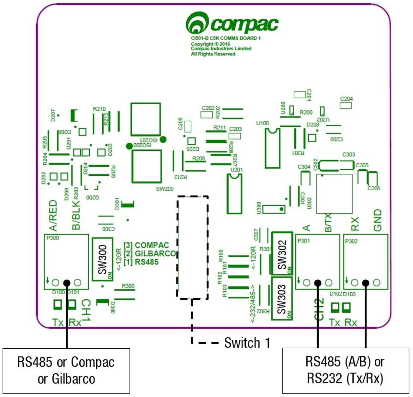
Switches 300, 302, and 303 are for RS485/RS232 Terminator application. Use the following table to configure these switches. Switch 300 is for channel 1, and switches 302 and 303 are for channel 2.
| SW300 | SW302 | SW303 | |
|---|---|---|---|
| RS485 (Channel 1) | ON | - | - |
| RS485 (Channel 2) | - | ON | OFF |
| RS232 (Channel 2) | - | OFF | ON |
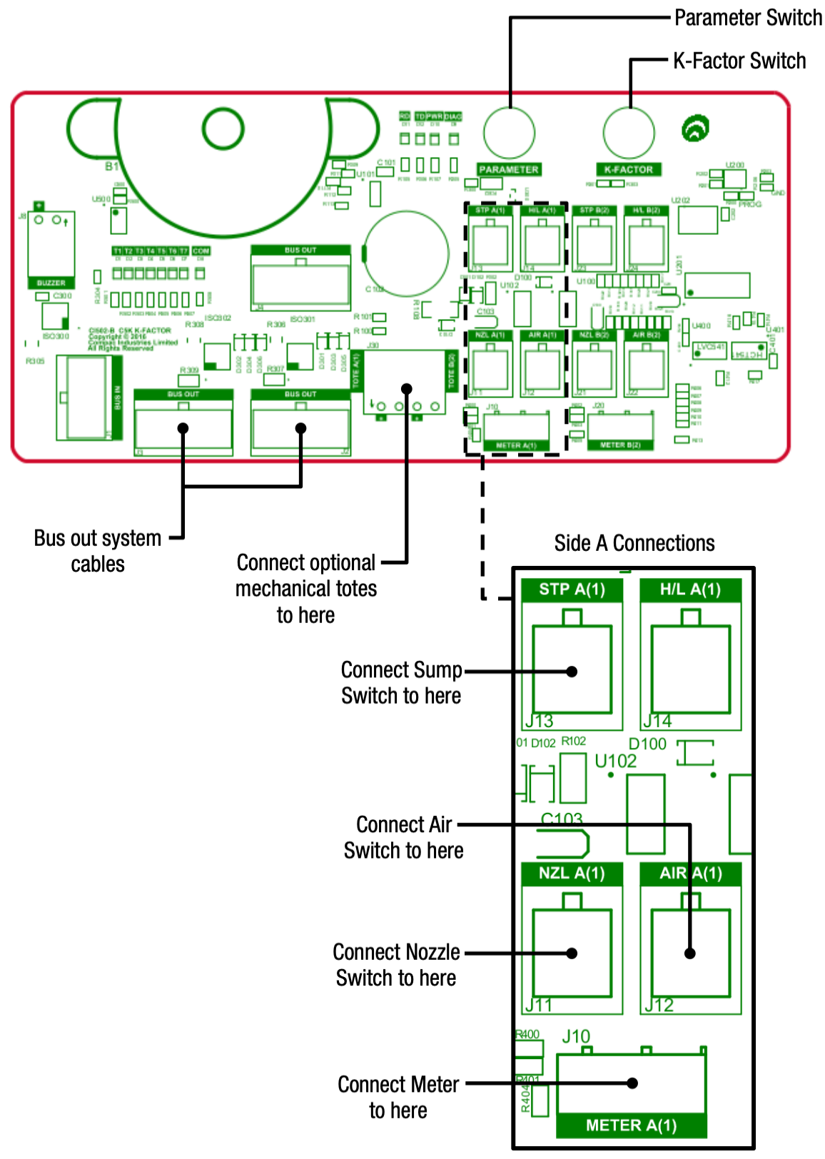
K-Factor Board
The K-factor is a calibration value that defines how many pulses a flow meter generates per unit of liquid—usually pulses per litre. The K-Factor board uses this value to accurately convert raw pulse signals into readable volume data. Both the Parameter switch and K-Factor switch are found on the K-Factor board. Meters and air switches are also connected to this board. See below for the location of these.
Terminal Board Connections
When using the C5000 electronics for dispenser application, as well as connecting the incoming mains, the external pump contactors will have to be connected to the terminal board.
Solenoids for side A and B are factory wired as shown below. (L) and (H) refer to low and hi flow respectively.
160 / 80 / 40 Litre Per Minute models
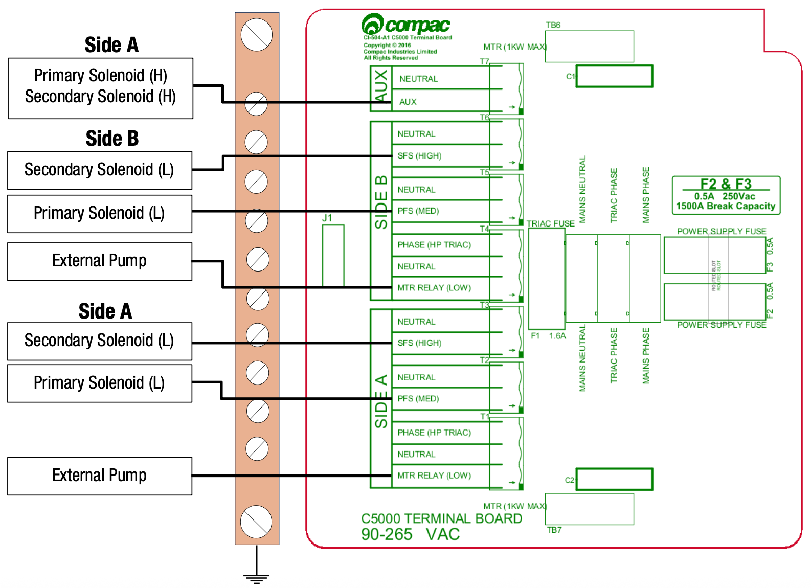
MMR160S
*NOTE: Only one external pump may be connected.
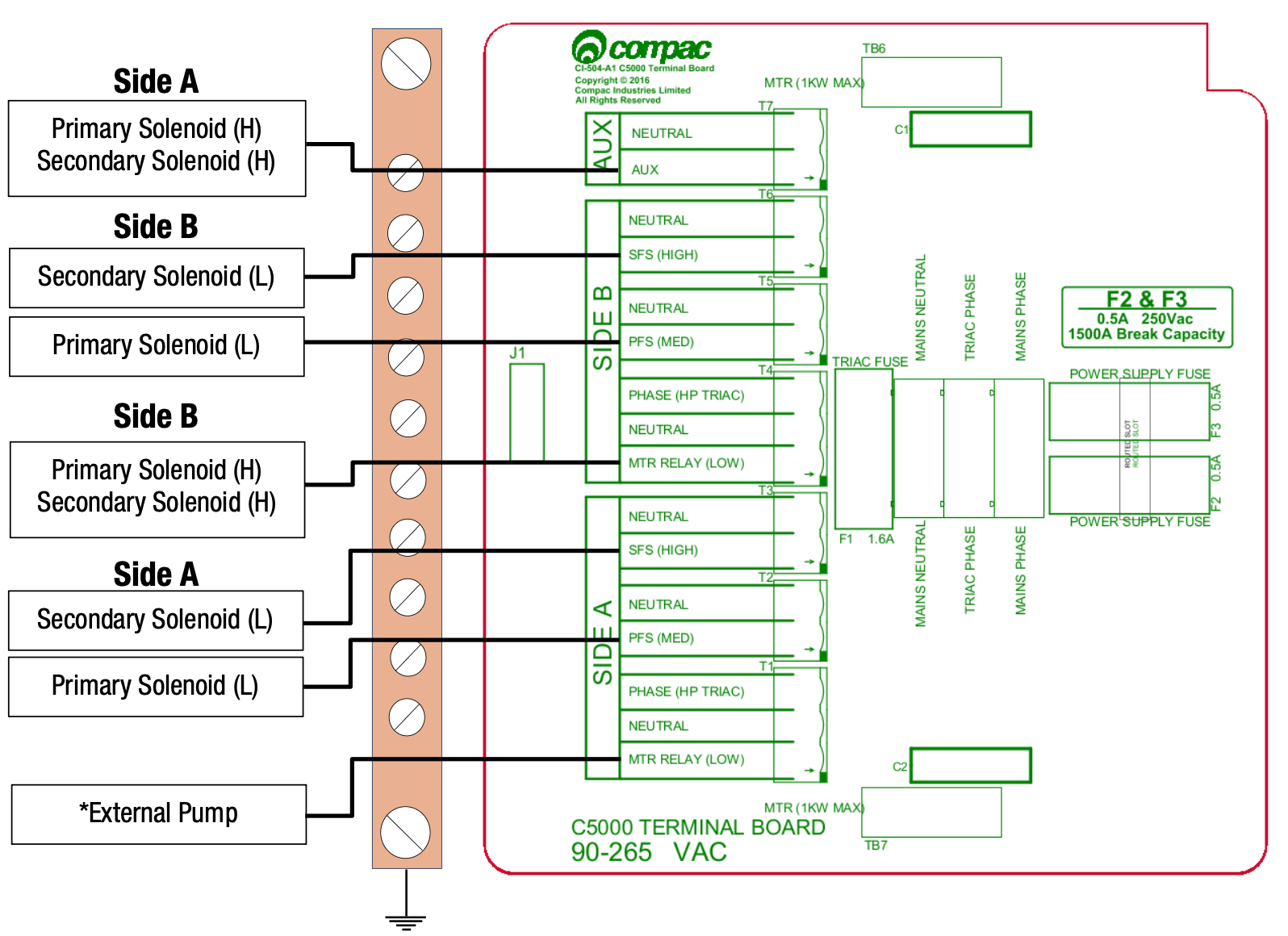
MR400S, MMRS400-160S, MMR400-80S
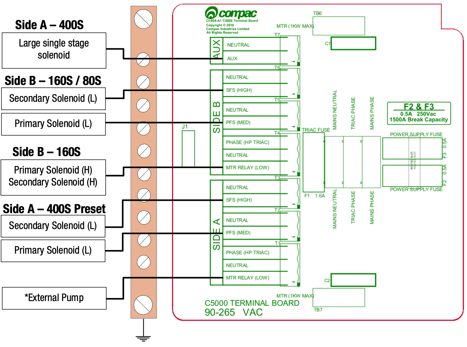
NOTE: (L) and (H) refer to low and hi flow respectively.
*NOTE: Only one external pump may be connected.
Setting up the C5000
The Compac C5000 is an advanced processor used in fuel dispensers and pumps, managing flow control, transaction processing, and system communications.
K-Factor Settings
The settings that can be accessed from the K-Factor switch are shown below. Not all of these will need to be changed during installation, therefore information on the following pages refers only to the settings that must be changed. Once the pump has been installed, if further customisation of the unit is desired, refer to the C5000 Manual. [** ADD LINK]
| Setting | Price display | Litres display |
|---|---|---|
| Dispenser settings. These are set in the factory and should not be changed. | c-A or c-b | ******* |
| Maximum flow | 9A **** or 9b **** | |
| K-Factor | FA or Fb | ******* |
| Configuration code. This is set at the factory and should not be changed. | c | ******* |
| Solenoid delay | SdA*** or Sdb*** | |
| Preset cutoff. This is available if a secondary solenoid is wired in. | PcA*** or Pcb*** | |
| Preset rounding | PrLA*** or PrLb*** PrHA*** or PrHb*** |
|
| Flow time out | n-A*** or n-b*** |
[** Doesn’t use seven segment numerals as on actual display]
Changing the K-Factor
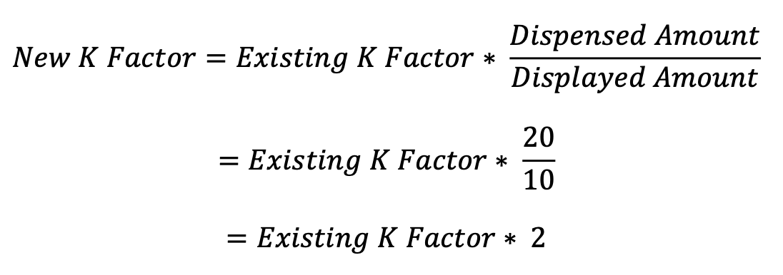
The K-Factor is used to calibrate product flow. It is a ratio of litres dispensed per revolution of the meter. The K-Factor may need to be calibrated after periods of time. To calibrate the pump, dispense fuel into a certified measuring container and compare the display value with the one dispensed.
Example:
Display shows 10.00 True volume 20.00
To calculate the correct K-Factor from the information above; firstly record the existing K-Factor.
To change the K-Factor, depress the K-Factor switch repeatedly until the following display is shown. To increment a digit, press and hold the parameter switch when the desired digit is flashing. Repeat this procedure for side B if applicable.

Changing the Solenoid Delay
This is the time delay from when the submersible pump starts to when the solenoids in the dispenser open to allow time for the leak detector to reset.
This is factory set by Compac at 005 (five seconds).
If problems are experienced with the leak detector tripping, firstly check that the solenoid delayis still set and then, if necessary, make it longer as follows.
To change the solenoid delay, depress the K-Factor switch repeatedly until the following display is shown. To increment a digit, press and hold the parameter switch when the desired digit is flashing. Repeat this procedure for side B if applicable.

Parameter Settings
The settings that can be accessed from the parameter switch are shown below. Not all of these will need to be changed during installation, therefore information on the following pages refers only to the settings that must be changed. Once the pump has been installed, if further customisation of the unit is desired, refer to the C5000 Manual.
| Setting | Price Display | Litres Display |
|---|---|---|
| Software Version – the pump will then run a segment test | P****** | P****** |
| Pump Number | PnA*** or Pnb*** | |
| Price | PA**** or Pb**** | |
| Pump Settings | bA**** or bb**** | |
| High-flow cut off | LFA*** | |
| Low-flow cut off | HFA*** | |
| b Setting. This is not currently in use and should not be changed | b**** | b**** |
| Electronic Totes | LA**** or dA**** Lb**** or dA**** |
L*****
|
Changing the Pump Number
If the parameter switch is continually depressed, the following menu to change the pump number will appear. Each side must be numbered between 1-99. Entering a pump number 0 will disable the pump.
To change the pump number, depress the parameter switch repeatedly until the following display is shown. To increment a digit, press and hold the parameter switch when the desired digit is flashing. Repeat this procedure for side B if applicable.

Changing the Price
The price must be set before the dispenser can be used, otherwise an error will be returned. Set the price in dollars per litre.
To change the price, depress the parameter switch repeatedly until the following display is shown. To increment a digit, press and hold the parameter switch when the desired digit is flashing. Repeat this procedure for side B if applicable.

Standalone Mode
In standalone operation, the dispenser will continue working when not connected to a controller. When in Standalone mode no authorisation of fills is required and so fills are simply initiated by removing the refuelling assembly from its holder. If standalone operation is inhibited, the dispenser will not work in standalone mode, regardless of whether the dispenser is ONLINE to a controller or not.
The dispenser ceases to work in standalone mode if connected to a controller, regardless of the position of standalone setting.
Generally, on retail forecourts the dispenser should be set-up for standalone operation. Hence, if the forecourt controller breaks down the dispensers can be set to work in standalone mode simply by turning them off then on again.
For unattended refuelling sites, the dispensers should not be able to work in standalone mode in the event of a controller failure. Therefore, the dispenser should be set-up to inhibit standalone operation.
This is set in the b code on the K factor switch. The b code to run Standalone without Dispenser Controller is 1000. The b code to inhibit Standalone is 0000.

Notes
Pump Controller
If the pump is connected to a controller, check that pump data and transaction information is being correctly uploaded to it. Refer to the controller manual for specific instructions regarding connection and setup.
Spare Fuses
In the event of a fuse blowing on the C5000 Power supply a bag of 3 is included in each flameproof box. Any fuses used from this bag should be replaced.
NOTE: There are three different ratings used. If replacing a fuse, ensure that the correct value is used.
Precautions if Using Generator Power
The power output from onsite generators can cause power spikes that may damage electrical
components within the cabinet. When connecting to sites powered by generators, please take
the following precautions:
-
Install a power conditioner. Although generators are fitted with power regulators, most are not filtered sufficiently for powering sensitive electrical components. We recommend installing a commercial power conditioner and/or UPS between the generator and the unit.
-
Before starting a generator, make sure the power to the unit is turned off. Start the generator, let the generator reach stable operating speed and wait 30 seconds before reconnecting the power to the unit.
-
For units where the generator starts and stops on demand, install a delay timer or PLC to automatically isolate the unit until the operating speed and consistent power output is achieved.
-
Isolate the unit before shutting down the generator.
Error messages
Compac dispensers and systems display error codes to alert users or technicians when something isn’t working as expected. Each code points to a specific issue — such as configuration errors, excessive flow, reverse flow, or problems with key components like the processor or K-Factor board. These codes are designed to speed up troubleshooting by clearly identifying the fault and often suggesting the required action (e.g. reconfiguring a setting, checking for leaks, or pressing a reset switch). If an error code appears, refer to the error message list to understand the cause and how to fix it. Quick action helps ensure the equipment runs safely and efficiently.
Visit the Error codes page to see the full list.
Conditions of Use
Before using or servicing the Compac C5000, you must read all relevant technical support material and follow all safety procedures — failure to do so may result in injury, damage, or poor performance. Compac accepts no liability for issues caused by incorrect use, unauthorised modifications, or conditions beyond its control. Read full Conditions of Use.
Validity
Compac Industries Limited reserves the right to revise or change product specifications at any time. This publication describes the state of the product at the time of publication and may not reflect the product at all times in the past or in the future.
Manufactured By
Compac Dispensers are designed and manufactured by
Compac Industries Limited
52 Walls Road, Penrose,
Auckland 1061, New Zealand P.O.
Box 12-417, Penrose, Auckland 1641,
New Zealand Phone:
+ 64 9 579 2094 Fax:
+ 64 9 579 0635
Email: [email protected]
Copyright ©2015 Compac Industries Limited, All Rights Reserved